1. Applications
2D data can be visualized on the "Map" page, and 3D data on the "Visualization" page.
DWG and DXF files can be used in equipment accuracy calibrations in the "Equipment" page section "Accuracy". By selecting a DWG or DXF file as a "KnownPoints file" in the project settings section "Equipment Accuracy Calibration", the file can be used as reference data in equipment calibration.
DWG and DXF files can be used as default drawings in the Truck app and the "Trucks" page by selecting the drawing in the project settings page section "Base Drawing".
DWG and DXF files can be used as border drawings for the project. This drawing will be visible in the cross-section view as vertical lines. By selecting a file in the project settings page section "Border Drawing", the vertical lines will always be visible when a cross-section view is opened.
DWG and DXF files can be assigned to a machine in the "Equipment" page section "ASSIGNMENTS" or in the "Map" page using the "Equipment" tab and selecting the "Assignments" subtab.
By adding "!BG.dxf" at the end of the DXF or DWG file, for example, "test_file!BG.dxf", Infrakit will interpret this file as a 2D drawing. The "!BG" also defines the file as a background map for the Novatron machine control system, but only DXF files can be used.
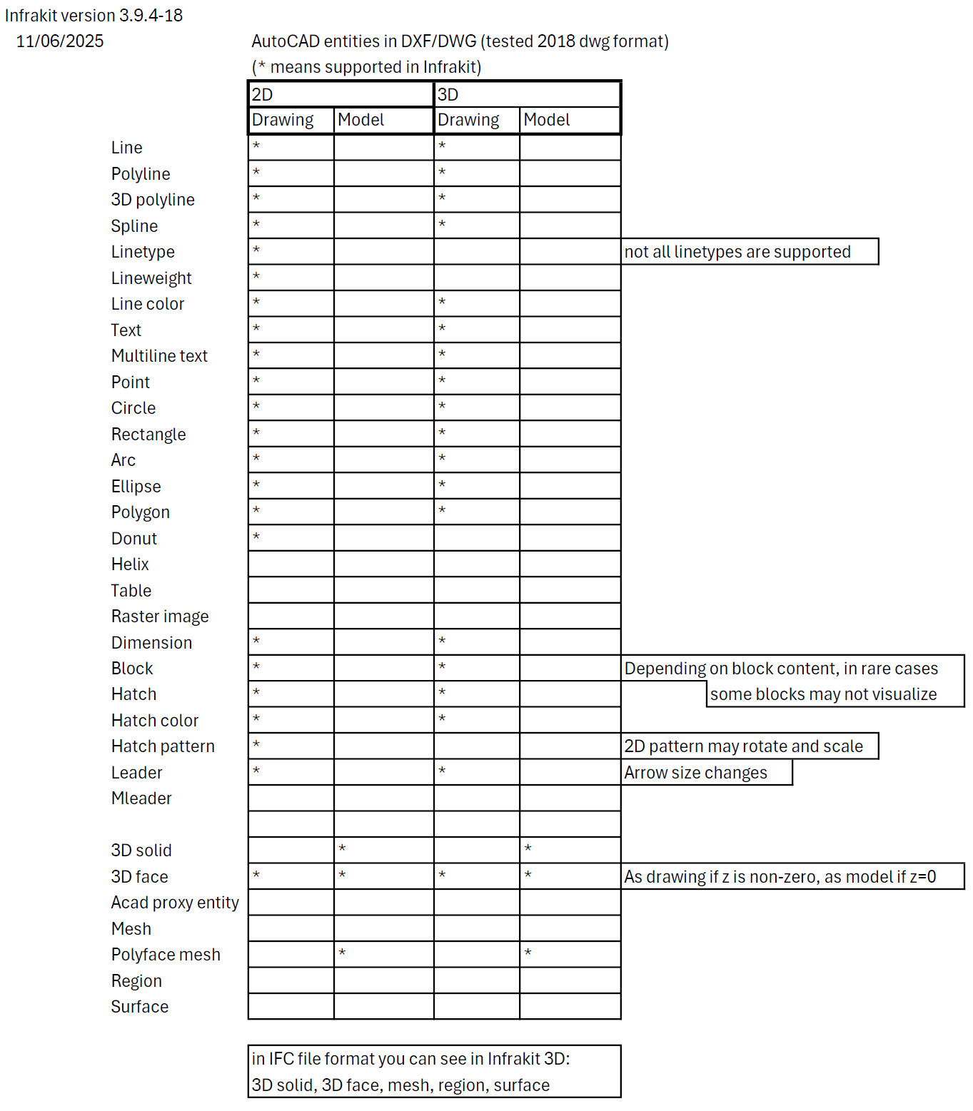
2. Supported Objects
In this section, the supported DWG and DXF objects that can be visualized in Infrakit are listed. These objects are AutoCAD entities that have been tested with the 2018 DWG format.
3. Line Colors
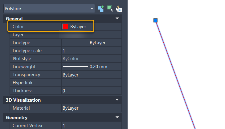
The color of DWG and DXF data is visualized in Infrakit based on the color that is defined for individual layers in the CAD program.
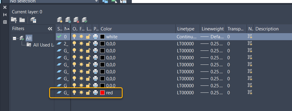
When a layer has been given a color, e.g. red, the objects that are on this layer and color choice property is ByLayer, the objects defined in this way appear as red in Infrakit.
If, on the other hand, the color is defined per object, the color will not be displayed correctly in Infrakit.
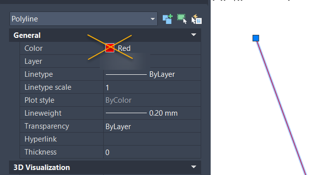
In general, it is recommended that the properties of e.g. lines representing the same category of objects are most conveniently managed via the layers and not as individual objects.