- Basic Functions
- Mouse Actions
- Supported File Formats
- Use Cases
- Frequently asked questions (FAQ)
- Troubleshooting
<< To Map page
1. Basic Functions ^
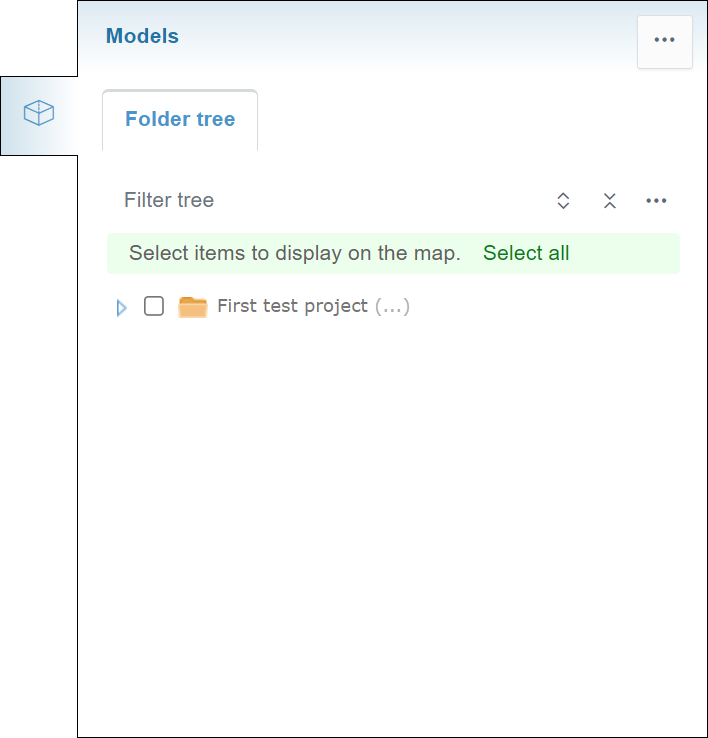
The tab contains one subtab, "Folder tree".
Folder Tree Subtab ^
General Features ^
By clicking the three-dot icon button, a box will appear.

In the "Point label" section, the user can determine what information is visible, considering point objects. Up to three values can be selected at the same time. "X", "Y" and, "Z" represent the coordinates of the point. "Code", "Line code", "Surface code", "Point number" and, "Point name" represent different metadata values of the point determined by the user.
Folder Tree Tools ^
Above the folder tree, different tools can be found to browse the folders.
In the "Filter tree" bar, the user can search folders or files from the folder tree.
By clicking the "Expand tree" button, the whole folder tree will be revealed.
By clicking the "Collapse tree" button, the folder tree will be collapsed so that only the root folder will be visible.
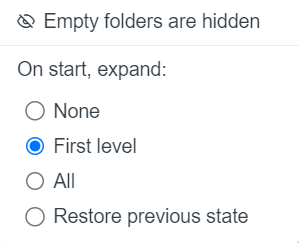
By clicking the "Tree settings" button, a box will appear.
As a default, empty folders in the folder tree are hidden, and this cannot be changed.
"On start, expand", the user can determine how the folder tree is shown after the browser page has been reloaded, for example, when the user logs in to Infrakit or refreshes the page. "None" means that only the root folder is shown; "First level" means that only the direct subfolders of the root folder will be shown; "All" means that all the folders in the folder tree will be shown; and "Restore previous state" means that the previous state of the folder tree will be restored.
Activating Models ^
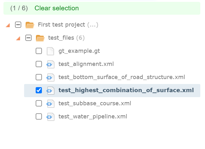
Models can be activated by checking the box next to the file name.
By clicking the file name, the user can readjust the map according to the model.
By clicking "Select all", the user can activate all the models uploaded to the project.
When models are activated, the "Clear Selection" tool becomes available.
By clicking "Clear selection", the user can deactivate all the activated models.
2. Mouse Actions ^
Different features and tools are provided when the right button on the mouse is clicked on folders, files, and models.
Folders ^
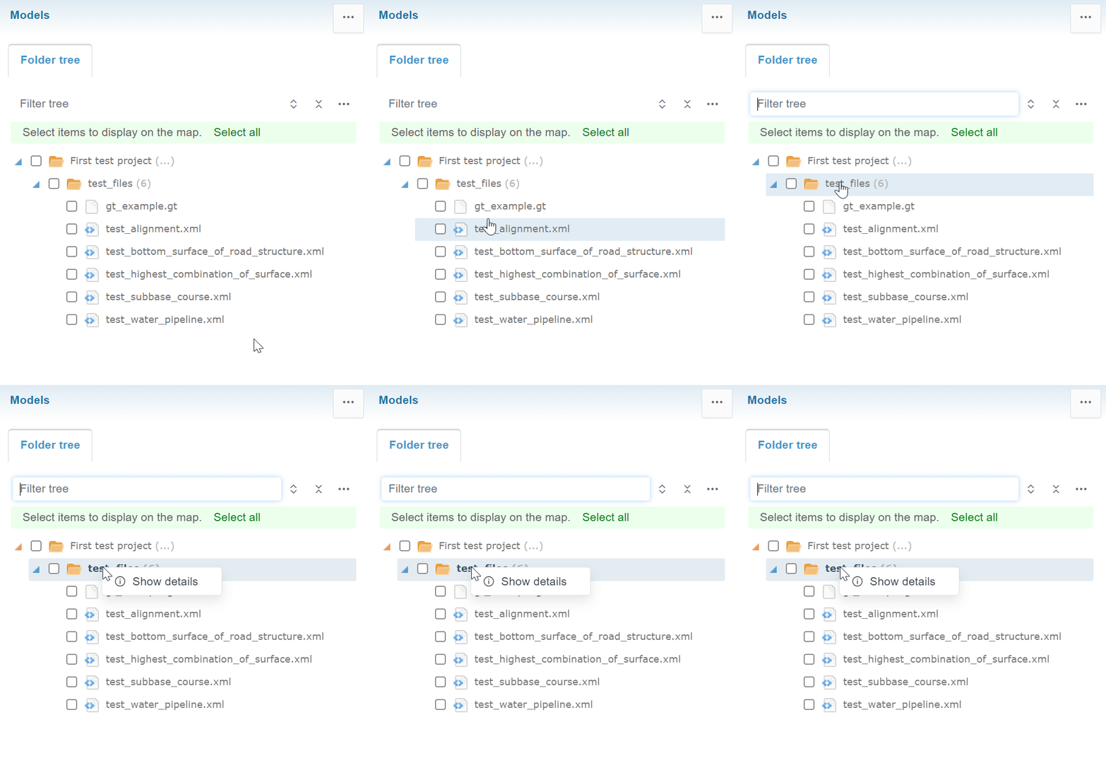
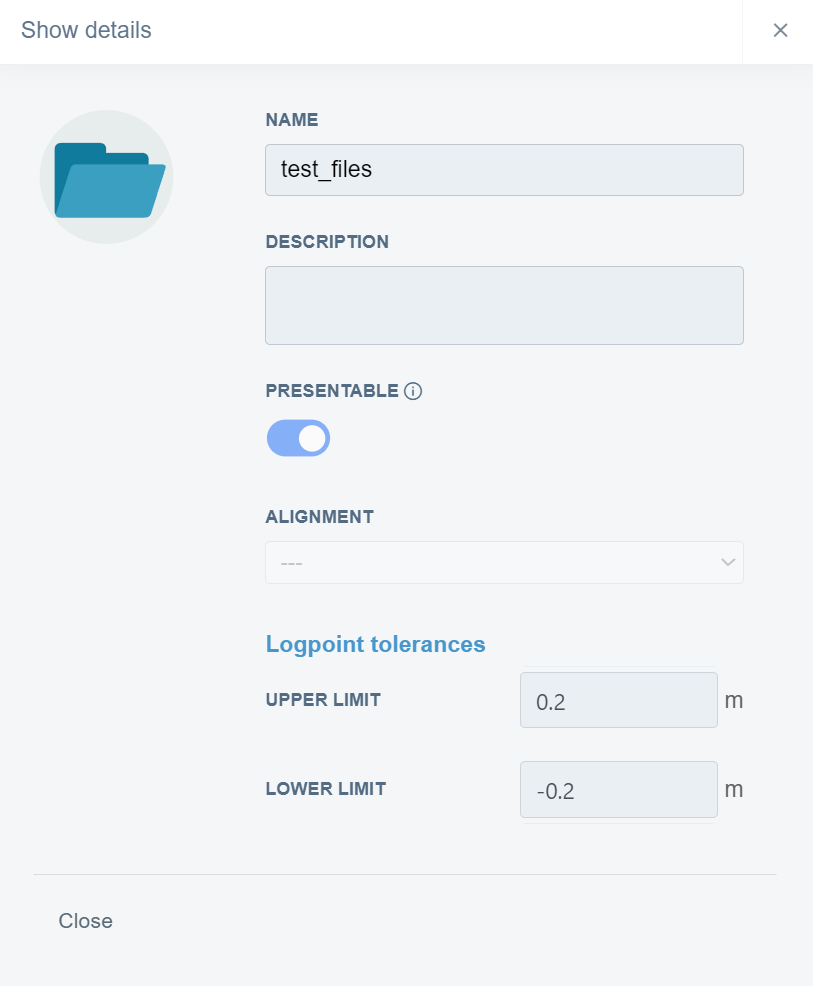
When a folder name is clicked in the folder tree with the right button on the mouse, an option appears.
By clicking "Show details", a box will open.
Files ^
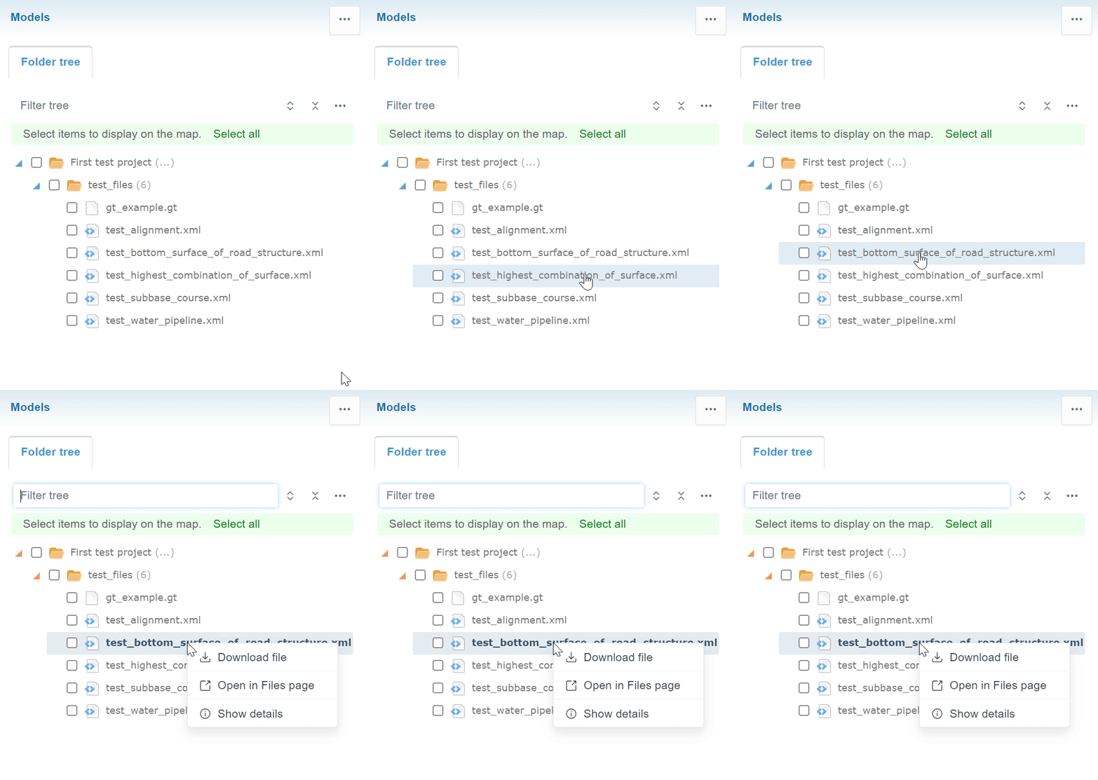
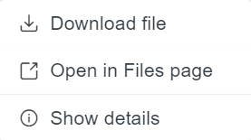
When a file name is clicked in the folder tree with the right button on the mouse, two options appear.
By clicking "Download", the user can download the model's file to local storage.
By clicking "Open in Files page", the user will be directed to the "Files" page in the folder where the file is located, and the file will be marked as selected.
By clicking "Show details", a bow will open.
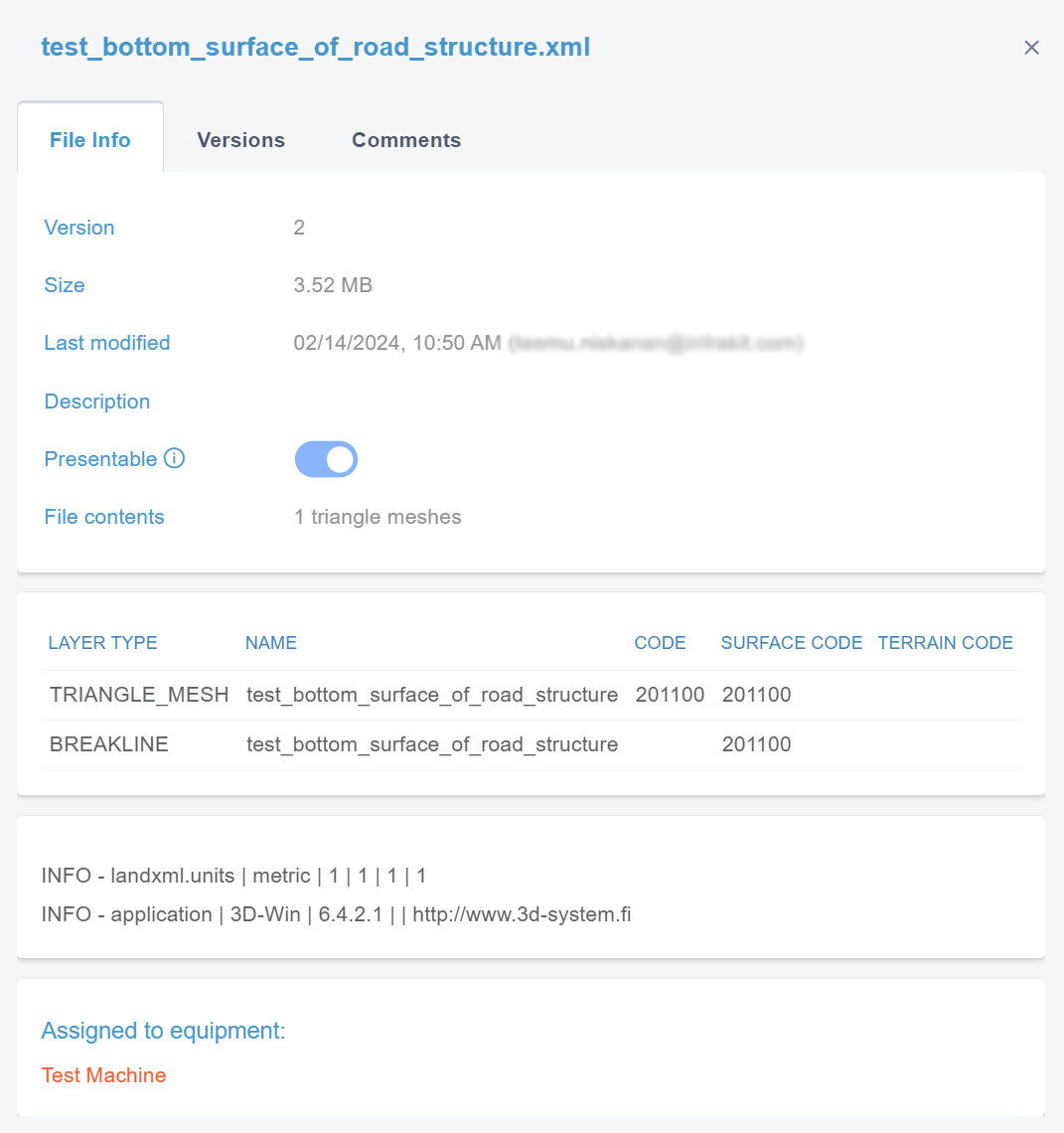
In the "File Info" tab, the user can observe the file's basic properties.
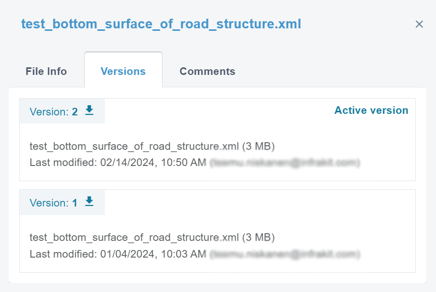
By clicking "Versions", a new view appears.
In this tab, the user can observe the version history and the current active version of the file.
By clicking the downward arrow next to the version number, the user can download the version.
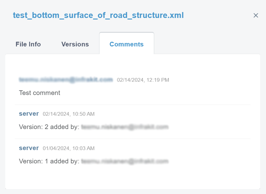
By clicking "Comments", a new view appears.
Surface Models ^
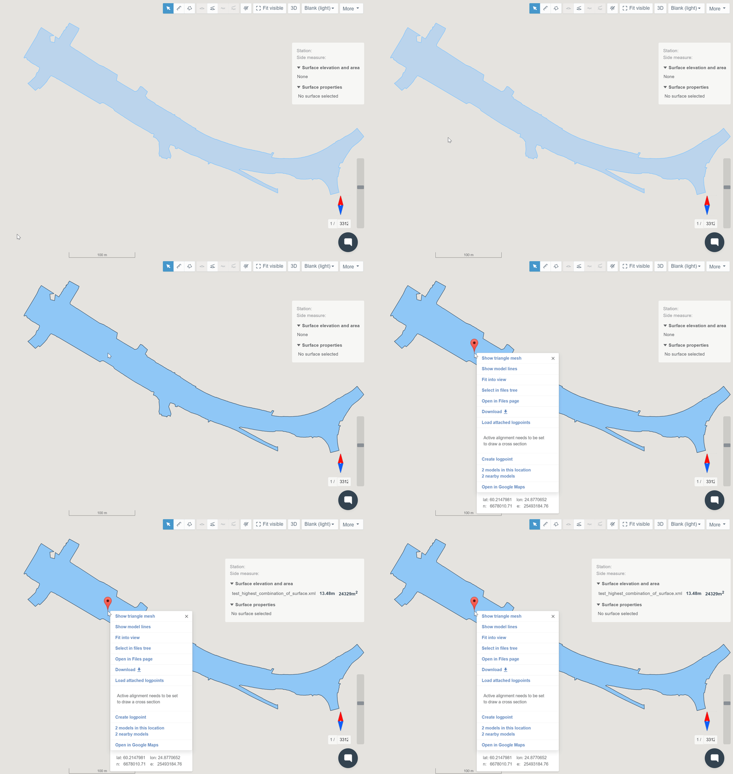
By clicking an activated surface model on the map with the right button on the mouse, a box will open.

By clicking "Show triangle mesh", the user can visualize the model's triangle mesh. By right-clicking the surface again, a new feature, "Hide triangle mesh", becomes available. By clicking this, the user can hide the visualized triangle mesh.
By clicking "Show model lines", the user can visualize the model's break lines. By right-clicking the surface again, a new feature, "Hide model lines", becomes available. By clicking this, the user can hide the visualized break lines.
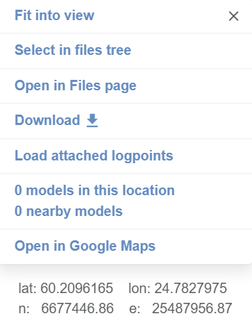
By clicking "Fit into view", the user can adjust the view according to the model.
By clicking "Select in files tree", the user can mark the model as selected in the folder tree.
By clicking "Open in Files page", the user will be directed to the "Files" page in the folder where the file is located, and the file will be marked as selected.
By clicking "Download", the user can download the model's file to local storage.
By clicking "Load attached logpoints", the user can activate the log points that are attached to the model.
If an alignment has been activated, two additional features will be available.
By clicking "Draw cross section", a new cross-section window will open based on the station location of the clicked point according to the alignment. The instructions for how to use cross-section view tools can be found on the "Map" page, section "Cross-Section Tools".
By clicking "Draw long section", a new long-section window will open based on the selected alignment. The instructions for how to use long-section view tools can be found on the "Map" page, section "Long-Section Tools".
By clicking "Create logpoint", a box will open.
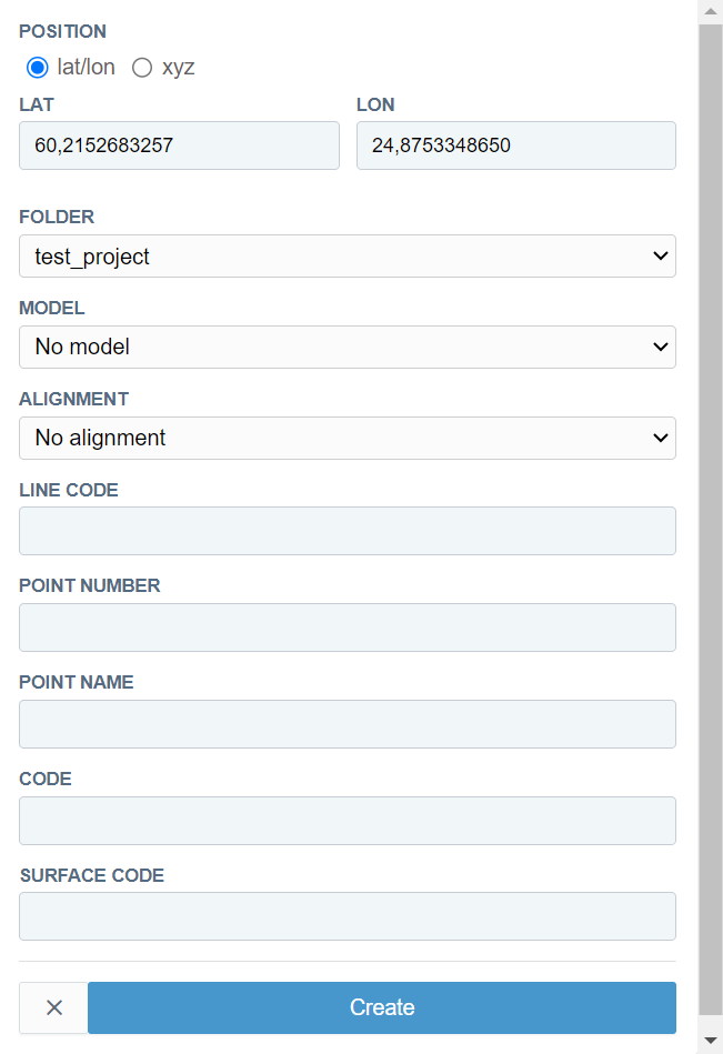
In the "POSITION" section, the user can determine how the location of the log point is inserted. By selecting "lat/lon", the user can define the location in latitude and longitude values in the "LAT" and "LON" bars. By selecting "xyz", the user can define location in xyz coordinates in the "X", "Y", and "Z" bars.
From the "FOLDER" drop-down bar, the user can select the folder where the log point will be located.
From the "MODEL" drop-down bar, the user can select a model to which the log point will be attached.
From the "ALIGNMENT" drop-down bar, the user can select an alignment to which the log point will be attached.
In the "LINE CODE" bar, the user can insert a line code for the log point.
In the "POINT NUMBER" bar, the user can insert a point number for the log point.
In the "POINT NAME" bar, the user can insert a point name for the log point.
In the "CODE" bar, the user can insert a code for the log point.
In the "SURFACE CODE" bar, the user can insert a surface code for the log point.
By clicking the "Create" button, the user can create a log point with inserted values.
By clicking the x icon button, the user can close the box without creating a log point.
By clicking "models in this location/nearby models", a box will open.
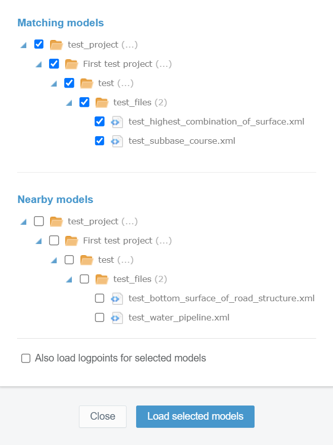
All the models that include the point that has been clicked on the map are visible in the "Matching models" section. All the nearby models are visible in the "Nearby models" section.
By checking the box next to the file name, the user can select the model.
By checking "Also load logpoints for selected models", the user can load the log points that are attached to the models. These log points will be visible on the map.
By clicking the "Load selected models" button, the user can load the selected models on the map.
By clicking the "Close" button, the user can close the box without loading models.
By clicking "Open in Google Maps", the user will be directed to the Google Maps website, where the clicked point is located.
Point Files ^
By clicking an activated point file on the map with the right button on the mouse, a box will open.
This box includes the same features and tools as in the section "Surface Models" except those specified for the surface models.
3. Supported File Formats ^
LandXML, IFC, DWG, DXF, Geonic (GT), SHP, GEO, KOF, CSV, PXY, IREDES XML, VGP, JXL, SOS
