InfraBIM folder structure is developed by buildingSMART Finland together with all key industry players of the region. Supporting material for this structure is found online. Linked site discusses the "holy trinity" of information modeling, including requirements, classification system and data exchange format:
https://buildingsmart.fi/en/infrabim-en/
In the link below you can download compressed folder structure with English classification names:
InfraBIM folder structure (ZIP)
Note! you can use same folder structure with or without classification system and modify it to needs of your project. However, this structure has some general ideas that make digital information management efficient.
Quick guide for placing information in InfraBIM folder structure
First make root folder in Infrakit files page by clicking "New folder" (point 1, in figure 1 below):

Figure 1. Make root folder in Infrakit
Following dialog opens, name the root folder and click create folder. Please see chapter "Naming convention" for guideline how to name the root folder.
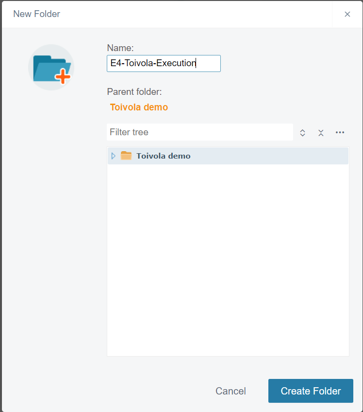
Figure 2. Name the folder in Infrakit
Simply drag and drop the folder structure ZIP to Infrakit web page. Upload dialog appears, confirm upload. When upload is done, file row turns green and dialog can be closed. If your desire to optimize the amount of root folders, simply select first level of subfolders and use "Move to" command in Infrakit (point 2 in figure 1). If you miss a lot of empty folders, ensure your "Hide empty folders" is not clicked (point 3 in figure 1).
Purpose of the first level subfolders:
00_Field: Fast access to reporting from field applications. Home for pictures, PDF reports, raw surveying and drone images
01_Process: Contracts, meetings, cost control, risk management, site journal
02_Quality: Deviation reports, Model-based quality assurance, checking of base stations, grade control and survey instruments.
03_Initial_data: Raw initial data, rock and soil from bore holes, base for measurements
04_Execution_model: Models structured by InfraBIM classification
05_Design_documents: Design drawings
06_Related: Safety, environment
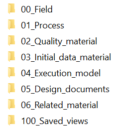
Figure 3. First level classification of data in first sub folder level
Naming conventions
The names of files and folders must be short and descriptive so that the file names clearly indicate the content. The names of files and folders must not contain spaces, letters ‘å’, ‘ä’ or ‘ö’, or other regional or special characters. The allowed characters are letters A–Z and a–z, numbers 0–9, and the underscore and hyphen. The maximum length of a directory path, file names included, is 200 characters. These rules consider many systems to be integrated.
Folders: Root folder is recommended to be named by Project id, short name and possible with purpose, like final design or execution. First level sub folders are classifying the material as visualized in figure 3. Second level sub-folders classifies data even further and typically starts by classes denoted by three digit numbers or alphabets. Third and fourth levels include the data content. It is not recommended to make fifth sub folder level.
Files: Files are optimized for several field use cases and constrains. Therefore it is a good practice to split models by structure. Large structures are also split by station. Recommended naming convention is described in the figure 4 below, where E1R1 identifies the route, YYP identifies the short name of structure, 500-900 station range, 201000 surface code, mm stands for terrain model code. For smaller projects some of the information may be self-explaining or otherwise not needed. Such information could be left of. However it is good practice to consider Route (Object code), Surface short name and Station range as minimum requirement to the file name. Files are placed to the folders divided by structures, so data is found by surface code even though it is not described in the filename.
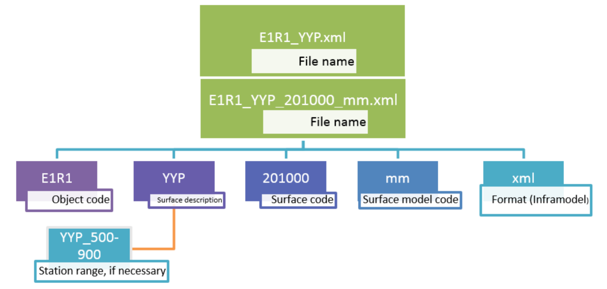
Figure 4. Naming system for file. Consider Object code, Surface short name and Station range as minimum requirement.
Relevant folders for Field app
00_Field/001_Photos/: All photos taken from site
00_Field/002_Survey/: Raw log points survey
00_Field/PDF_reports_in/: Folder for filled PDF reports, if user is unsure where to send them
01_Process/015_Risk_management/: identified risks to view / send
02_Quality_material/211_Structural_elements/: load press test reports to view / send
04_Execution_model/9001_Control_points/: points for equipment accuracy checking
04_Execution_model/: Models and drawings to view. If you have several sections in your project it is recommended to copy suggested Execution model structure for each section (04_Execution_model\S1\0000_..)
05_Design_documents/: Design PDF's to view
06_Related_material/610_Safety/: Safety reports to view / send
Relevant folders for setting up the project
01_Process/090_PDF_Templates/: folder for PDF templates filled on site
04_Excecution_model/: Models by structure. Recommended format is landXML that can be distributed to many connected systems. One structure (layer) in one file including surface breaklines in source data. Alternative method is to use Stringline layers extension. Alignments are placed separately to folder "0000_Alignments".
04_Excecution_model/9001_Control_points/: Folder for measurement base, temporary control points and points for grade benching. Recommended code for grade benching point is "9999". It is recommended to share this folder for orientation of total stations on site.
04_Excecution_model/9002_Reference_drawings/: Folder for reference drawings for grade control. Typically one optimized DXF file is good for many systems to cover the overall situation on site.
04_Excecution_model/9003_Avoidance_zones/: Folder for underground electric cables and similar. Could be used to create warnings on grade control systems.
Data flow from Infrakit to Field equipment
Field equipment can be for example one of the listed systems: machine control, total stations, RTK survey kit, tablet computer, XR headsets, etc. Prerequisite is that equipment is supported and is integrated to Infrakit project (see separate vendor specific instructions)
Generic data flow
Up-to-date models are addressed to individual machines from "Vehicles" page of Infrakit OFFICE system. Go to "Manage rights" tab and choose model files and folders for machine as desired. landXML source files go directly to several vendors but some require file flipping. Topcon file flipping utility is integrated to the Infrakit and selected files are automatically converted for Topcon system. Leica and Topcon accept coordinate system set in the control unit only. For Xsite system site calibration and other configurations are applied when they exist in the root folder of the project.
Trimble
Trimble file flipper is external tool at the time of writing so it is required to convert landXML source files to Trimble formats manually.
For GCS900 system: Convert SVD/SVL/CAL files and place them with same name to landXML source file to relevant subfolder in /04_Execution_model/ folder. SVD includes TIN, SVL lineworks and CAL file site calibration.
For Earthworks system: Convert DSZ file and place it to dedicated "/04_Execution_model/EW_models/" folder. This is because file management in Trimble Connected Community differs between generations and it does not support machine specific folders for Earthworks generation. DSZ includes TIN/linework and site calibration all in one file. Name the DSZ file same to source landXML file and as-built is connected to source file when arrived.
As-built from Field equipment to Infrakit
Field equipment can be for example one of the listed systems: machine control, total stations, RTK survey kit, high precision tablet computer, etc. Prerequisite is that equipment is supported and is integrated to Infrakit project (see separate vendor specific instructions)
Generic data flow
Points from equipment are divided into two categories. First, points that have reference to model assigned for equipment are considered as as-built points. As-built points are aggregated in Infrakit and used to indicate the quality and progress of the earthmoving process.
The log points that are measured without connection to model are considered as log points that may represent for example old cable found underground. These points are not used for tracking quality and progress automatically.
For most systems as-built and log points are synchronized automatically with vendor specific frequency.